The following sections provide information about Multiple Spanning-Tree Protocol (MSTP):
Multiple Spanning-Tree Protocol (MSTP), which uses Rapid Spanning-Tree Protocol (RSTP) for rapid convergence, enables multiple VLANs to be grouped into and mapped to the same spanning-tree instance, reducing the number of spanning-tree instances that are needed to support many VLANs. The MSTP provides for multiple forwarding paths for data traffic, enables load balancing, and reduces the number of spanning-tree instances that are required to support many VLANs. It improves the fault tolerance of the network because a failure in one instance (forwarding path) does not affect other instances (forwarding paths).
The multiple spanning-tree (MST) implementation is based on the IEEE 802.1s standard.
The most common initial deployment of MSTP is in the backbone and distribution layers of a Layer 2 switched network. This deployment provides the highly available network that is required in a service-provider environment.
When the device is in the MST mode, the RSTP, which is based on IEEE 802.1w, is automatically enabled. The RSTP provides rapid convergence of the spanning tree through explicit handshaking that eliminates the IEEE 802.1D forwarding delay and quickly transitions root ports and designated ports to the forwarding state.
Both MSTP and RSTP improve the spanning-tree operation and maintain backward compatibility with equipment that is based on the (original) IEEE 802.1D spanning tree, with existing Cisco-proprietary Multiple Instance STP (MISTP), and with existing Cisco PVST+ and rapid per-VLAN spanning-tree plus (Rapid PVST+).
A device stack appears as a single spanning-tree node to the rest of the network, and all stack members use the same device ID.
Speed | Path Cost Value |
|---|---|
10 Mb/s | 2,000,000 |
100 Mb/s | 200,000 |
1 Gb/s | 20,000 |
10 Gb/s | 2,000 |
100 Gb/s | 200 |
The switch maintains a spanning-tree instance for the group of VLANs mapped to it. A device ID, consisting of the switch priority and the switch MAC address, is associated with each instance. For a group of VLANs, the switch with the lowest device ID becomes the root switch.
When you configure a switch as the root, you modify the switch priority from the default value (32768) to a significantly lower value so that the switch becomes the root switch for the specified spanning-tree instance. When you enter this command, the switch checks the switch priorities of the root switches. Because of the extended system ID support, the switch sets its own priority for the specified instance to 24576 if this value will cause this switches to become the root for the specified spanning-tree instance.
If any root switch for the specified instance has a switch priority lower than 24576, the switch sets its own priority to 4096 less than the lowest switch priority. (4096 is the value of the least-significant bit of a 4-bit switch priority value. For more information, see Bridge ID, Switch Priority, and Extended System ID.
If your network consists of switches that support and do not support the extended system ID, it is unlikely that the switch with the extended system ID support will become the root switch. The extended system ID increases the switch priority value every time the VLAN number is greater than the priority of the connected switches running older software.
The root switch for each spanning-tree instance should be a backbone or distribution switch. Do not configure an access switch as the spanning-tree primary root.
Use the diameter keyword, which is available only for MST instance 0, to specify the Layer 2 network diameter (that is, the maximum number of switch hops between any two end stations in the Layer 2 network). When you specify the network diameter, the switch automatically sets an optimal hello time, forward-delay time, and maximum-age time for a network of that diameter, which can significantly reduce the convergence time. You can use the hello keyword to override the automatically calculated hello time.
For switches to participate in multiple spanning-tree (MST) instances, you must consistently configure the switches with the same MST configuration information. A collection of interconnected switches that have the same MST configuration comprises an MST region.
The MST configuration controls to which MST region each device belongs. The configuration includes the name of the region, the revision number, and the MST VLAN-to-instance assignment map. You configure the device for a region by specifying the MST region configuration on it. You can map VLANs to an MST instance, specify the region name, and set the revision number. For instructions and an example, select the "Specifying the MST Region Configuration and Enabling MSTP" link in Related Topics.
A region can have one or multiple members with the same MST configuration. Each member must be capable of processing RSTP bridge protocol data units (BPDUs). There is no limit to the number of MST regions in a network, but each region can support up to spanning-tree instances with the Cisco Catalyst 9500 Series Switches (C9500-12Q, C9500-16X, C9500-24Q, C9500-40X models) and 64 spanning-tree instances with the Cisco Catalyst 9500 Series High Performance Switches (C9500-32C, C9500-32QC, C9500-48Y4C, C9500-24Y4C models) . Instances can be identified by any number in the range from 0 to 4094. You can assign a VLAN to only one spanning-tree instance at a time.
The IST connects all the MSTP switches in a region. When the IST converges, the root of the IST becomes the CIST regional root. It is the switch within the region with the lowest device ID and path cost to the CIST root. The CIST regional root is also the CIST root if there is only one region in the network. If the CIST root is outside the region, one of the MSTP switches at the boundary of the region is selected as the CIST regional root.
When an MSTP switch initializes, it sends BPDUs claiming itself as the root of the CIST and the CIST regional root, with both of the path costs to the CIST root and to the CIST regional root set to zero. The switch also initializes all of its MST instances and claims to be the root for all of them. If the switch receives superior MST root information (lower device ID, lower path cost, and so forth) than currently stored for the port, it relinquishes its claim as the CIST regional root.
During initialization, a region might have many subregions, each with its own CIST regional root. As switches receive superior IST information, they leave their old subregions and join the new subregion that contains the true CIST regional root. All subregions shrink except for the one that contains the true CIST regional root.
For correct operation, all switches in the MST region must agree on the same CIST regional root. Therefore, any two switches in the region only synchronize their port roles for an MST instance if they converge to a common CIST regional root.
If there are multiple regions or legacy IEEE 802.1D switches within the network, MSTP establishes and maintains the CST, which includes all MST regions and all legacy STP switches in the network. The MST instances combine with the IST at the boundary of the region to become the CST.
The IST connects all the MSTP switches in the region and appears as a subtree in the CIST that encompasses the entire switched domain. The root of the subtree is the CIST regional root. The MST region appears as a virtual switch to adjacent STP switches and MST regions.
Only the CST instance sends and receives BPDUs, and MST instances add their spanning-tree information into the BPDUs to interact with neighboring switches and compute the final spanning-tree topology. Because of this, the spanning-tree parameters that are related to BPDU transmission (for example, hello time, forward time, max-age, and max-hops) are configured only on the CST instance but affect all MST instances. Parameters that are related to the spanning-tree topology (for example, switch priority, port VLAN cost, and port VLAN priority) can be configured on both the CST instance and the MST instance.
MSTP switches use Version 3 RSTP BPDUs or IEEE 802.1D STP BPDUs to communicate with legacy IEEE 802.1D devices. MSTP switches use MSTP BPDUs to communicate with MSTP devices.
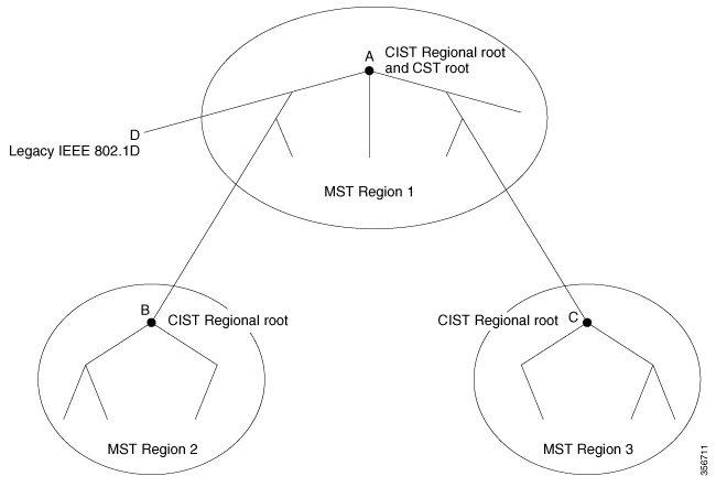
This figure displays three MST regions and a legacy IEEE 802.1D device (D). The CIST regional root for region 1 (A) is also the CIST root. The CIST regional root for region 2 (B) and the CIST regional root for region 3 (C) are the roots for their respective subtrees within the CIST. The RSTP runs in all regions.
The IST and MST instances do not use the message-age and maximum-age information in the configuration BPDU to compute the spanning-tree topology. Instead, they use the path cost to the root and a hop-count mechanism similar to the IP time-to-live (TTL) mechanism.
By using the spanning-tree mst max-hops global configuration command, you can configure the maximum hops inside the region and apply it to the IST and all MST instances in that region. The hop count achieves the same result as the message-age information (triggers a reconfiguration). The root switch of the instance always sends a BPDU (or M-record) with a cost of 0 and the hop count set to the maximum value. When a switch receives this BPDU, it decrements the received remaining hop count by one and propagates this value as the remaining hop count in the BPDUs it generates. When the count reaches zero, the switch discards the BPDU and ages the information that is held for the port.
The message-age and maximum-age information in the RSTP portion of the BPDU remain the same throughout the region, and the same values are propagated by the region designated ports at the boundary.
If there is a legacy STP device on the segment, messages are always considered external.
The other change from the Cisco prestandard implementation is that the CIST regional root device ID field is now inserted where an RSTP or legacy IEEE 802.1Q device has the sender device ID. The whole region performs like a single virtual device by sending a consistent sender device ID to neighboring devices. In this example, Switch C would receive a BPDU with the same consistent sender device ID of root, whether or not A or B is designated for the segment.
The Cisco implementation of the IEEE MST standard includes features required to meet the standard, as well as some of the desirable prestandard functionality that is not yet incorporated into the published standard.

Because automatic detection of prestandard devices can fail, you can use an interface configuration command to identify prestandard ports. A region cannot be formed between a standard and a prestandard device, but they can interoperate by using the CIST. Only the capability of load-balancing over different instances is lost in that particular case. The CLI displays different flags depending on the port configuration when a port receives prestandard BPDUs. A syslog message also appears the first time a device receives a prestandard BPDU on a port that has not been configured for prestandard BPDU transmission.
We recommend that you minimize the interaction between standard and prestandard MST implementations.

This feature is not yet present in the IEEE MST standard, but it is included in this Cisco IOS release. The software checks the consistency of the port role and state in the received BPDUs to detect unidirectional link failures that could cause bridging loops.
When a designated port detects a conflict, it keeps its role, but reverts to the discarding state because disrupting connectivity in case of inconsistency is preferable to opening a bridging loop.
A switch stack appears as a single spanning-tree node to the rest of the network, and all stack members use the same bridge ID for a given spanning tree. The bridge ID is derived from the MAC address of the device.
The active switch is the stack root when the stack is the root of the network and no root selection has been made within the stack.
If the switch stack is the spanning-tree root and the active switch fails or leaves the stack, the standby switch becomes the new active switch, bridge IDs remain the same, and a spanning-tree reconvergence might occur.
If a device that does not support MSTP is added to a switch stack that does support MSTP or the reverse, the device is put into a version mismatch state. If possible, the device is automatically upgraded or downgraded to the same version of software that is running on the switch stack.
A device running MSTP supports a built-in protocol migration mechanism that enables it to interoperate with legacy IEEE 802.1D devices. If this device receives a legacy IEEE 802.1D configuration BPDU (a BPDU with the protocol version set to 0), it sends only IEEE 802.1D BPDUs on that port. An MSTP device also can detect that a port is at the boundary of a region when it receives a legacy BPDU, an MSTP BPDU (Version 3) associated with a different region, or an RSTP BPDU (Version 2).
However, the device does not automatically revert to the MSTP mode if it no longer receives IEEE 802.1D BPDUs because it cannot detect whether the legacy switch has been removed from the link unless the legacy switch is the designated device. A device might also continue to assign a boundary role to a port when the device to which this device is connected has joined the region. To restart the protocol migration process (force the renegotiation with neighboring devices), use the clear spanning-tree detected-protocols privileged EXEC command.
If all the legacy switches on the link are RSTP devices, they can process MSTP BPDUs as if they are RSTP BPDUs. Therefore, MSTP devices send either a Version 0 configuration and TCN BPDUs or Version 3 MSTP BPDUs on a boundary port. A boundary port connects to a LAN, the designated device of which is either a single spanning-tree switch or a switch with a different MST configuration.
The RSTP takes advantage of point-to-point wiring and provides rapid convergence of the spanning tree. Reconfiguration of the spanning tree can occur in less than 1 second (in contrast to 50 seconds with the default settings in the IEEE 802.1D spanning tree).
Operational Status | STP Port State (IEEE 802.1D) | RSTP Port State | Is Port Included in the Active Topology? |
|---|---|---|---|
Enabled | Blocking | Discarding | No |
Enabled | Listening | Discarding | No |
Enabled | Learning | Learning | Yes |
Enabled | Forwarding | Forwarding | Yes |
Disabled | Disabled | Discarding | No |
To be consistent with Cisco STP implementations, this guide defines the port state as blocking instead of discarding. Designated ports start in the listening state.

The RSTP provides for rapid recovery of connectivity following the failure of a device, a device port, or a LAN. It provides rapid convergence for edge ports, new root ports, and ports connected through point-to-point links as follows:

When the device receives a proposal message on one of its ports and that port is selected as the new root port, the RSTP forces all other ports to synchronize with the new root information.
The device is synchronized with superior root information that is received on the root port if all other ports are synchronized. An individual port on the device is synchronized if:
If a designated port is in the forwarding state and is not configured as an edge port, it transitions to the blocking state when the RSTP forces it to synchronize with new root information. In general, when the RSTP forces a port to synchronize with root information and the port does not satisfy any of the above conditions, its port state is set to blocking.
The RSTP BPDU format is the same as the IEEE 802.1D BPDU format except that the protocol version is set to 2. A new 1-byte Version 1 Length field is set to zero, which means that no version 1 protocol information is present.
Bit | Function |
|---|---|
0 | Topology change (TC) |
1 | Proposal |
2–3: 00 01 10 11 | Port role: Unknown Alternate port Root port Designated port |
4 | Learning |
5 | Forwarding |
6 | Agreement |
7 | Topology change acknowledgement (TCA) |
The sending device sets the proposal flag in the RSTP BPDU to propose itself as the designated device on that LAN. The port role in the proposal message is always set to the designated port.
The sending device sets the agreement flag in the RSTP BPDU to accept the previous proposal. The port role in the agreement message is always set to the root port.
The RSTP does not have a separate topology change notification (TCN) BPDU. It uses the topology change (TC) flag to show the topology changes. However, for interoperability with IEEE 802.1D devices, the RSTP device processes and generates TCN BPDUs.
The learning and forwarding flags are set according to the state of the sending port.
If a port receives superior root information (lower device ID, lower path cost, and so forth) than currently stored for the port, the RSTP triggers a reconfiguration. If the port is proposed and is selected as the new root port, RSTP forces all the other ports to synchronize.
If the BPDU received is an RSTP BPDU with the proposal flag set, the device sends an agreement message after all of the other ports are synchronized. If the BPDU is an IEEE 802.1D BPDU, the device does not set the proposal flag and starts the forward-delay timer for the port. The new root port requires twice the forward-delay time to transition to the forwarding state.
If the superior information that is received on the port causes the port to become a backup or alternate port, RSTP sets the port to the blocking state but does not send the agreement message. The designated port continues sending BPDUs with the proposal flag set until the forward-delay timer expires, at which time the port transitions to the forwarding state.
If a designated port receives an inferior BPDU (such as a higher device ID or a higher path cost than currently stored for the port) with a designated port role, it immediately replies with its own information.
A device running MSTP supports a built-in protocol migration mechanism that enables it to interoperate with legacy IEEE 802.1D devices. If this device receives a legacy IEEE 802.1D configuration BPDU (a BPDU with the protocol version set to 0), it sends only IEEE 802.1D BPDUs on that port. An MSTP device also can detect that a port is at the boundary of a region when it receives a legacy BPDU, an MST BPDU (Version 3) associated with a different region, or an RST BPDU (Version 2).
However, the device does not automatically revert to the MSTP mode if it no longer receives IEEE 802.1D BPDUs because it cannot detect whether the legacy switch has been removed from the link unless the legacy switch is the designated device. A device also might continue to assign a boundary role to a port when the device to which it is connected has joined the region.
Feature | Default Setting |
|---|---|
Spanning-tree mode | |
Device priority (configurable on a per-CIST port basis) | 32768 |
Spanning-tree port priority (configurable on a per-CIST port basis) | 128 |
Spanning-tree port cost (configurable on a per-CIST port basis) | |
Hello time | |
Forward-delay time | |
Maximum-aging time | 20 seconds |
Maximum hop count | 20 hops |
The following sections provide information about configuring MSTP and MSTP parameters:
For two or more switches to be in the same MST region, they must have the same VLAN-to-instance mapping, the same configuration revision number, and the same name.
A region can have one member or multiple members with the same MST configuration; each member must be capable of processing RSTP BPDUs. There is no limit to the number of MST regions in a network, but each region can only support up to spanning-tree instances with the Cisco Catalyst 9500 Series Switches and 64 spanning-tree instances with the Cisco Catalyst 9500 Series Switches - High Performance . You can assign a VLAN to only one spanning-tree instance at a time.
| Command or Action | Purpose |
|---|---|
Step 1 | enable |
Device> enableEnables privileged EXEC mode.
Enter your password if prompted.
Device# configure terminalEnters global configuration mode.
Device(config)# spanning-tree mst configurationEnters MST configuration mode.
Device(config-mst)# instance 1 vlan 10-20Device(config-mst)# name region1 Specifies the configuration name. The name string has a maximum length of 32 characters and is case sensitive.
Device(config-mst)# revision 1Specifies the configuration revision number. The range is 0 to 65535.
Device(config-mst)# show pendingVerifies your configuration by displaying the pending configuration.
Device(config-mst)# exitApplies all changes, and returns to global configuration mode.
Device(config)# spanning-tree mode mstEnables MSTP. RSTP is also enabled.
Changing spanning-tree modes can disrupt traffic because all spanning-tree instances are stopped for the previous mode and restarted in the new mode.
You cannot run both MSTP and PVST+ or both MSTP and Rapid PVST+ at the same time.
Device(config)# endReturns to privileged EXEC mode.
To configure the root device, perform this procedure:
| Command or Action | Purpose |
|---|---|
Step 1 | enable |
Device> enableEnables privileged EXEC mode.
Enter your password if prompted.
Device# configure terminalEnters global configuration mode.
Device(config)# spanning-tree mst 0 root primaryConfigures a device as the root device.
For instance-id , you can specify a single instance, a range of instances separated by a hyphen, or a series of instances separated by a comma. The range is 0 to 4094.
Device(config)# endReturns to privileged EXEC mode.
When you configure a device with the extended system ID support as the secondary root, the device priority is modified from the default value (32768) to 28672. The device is then likely to become the root device for the specified instance if the primary root device fails. This is assuming that the other network devices use the default device priority of 32768 and therefore are unlikely to become the root device.
You can execute this command on more than one device to configure multiple backup root devices. Use the same network diameter and hello-time values that you used when you configured the primary root device with the spanning-tree mst instance-id root primary global configuration command.
To configure a secondary root device, perform this procedure:
| Command or Action | Purpose |
|---|---|
Step 1 | enable |
Device> enableEnables privileged EXEC mode.
Enter your password if prompted.
Device# configure terminalEnters global configuration mode.
Device(config)# spanning-tree mst 0 root secondaryConfigures a devices as the secondary root device.
For instance-id , you can specify a single instance, a range of instances separated by a hyphen, or a series of instances separated by a comma. The range is 0 to 4094.
Device(config)# endReturns to privileged EXEC mode.
If a loop occurs, the MSTP uses the port priority when selecting an interface to put into the forwarding state. You can assign higher priority values (lower numerical values) to interfaces that you want selected first and lower priority values (higher numerical values) that you want selected last. If all interfaces have the same priority value, the MSTP puts the interface with the lowest interface number in the forwarding state and blocks the other interfaces.
If the device is a member of a switch stack, you must use the spanning-tree mst [ instance-id ] cost cost interface configuration command instead of the spanning-tree mst [ instance-id ] port-priority priority interface configuration command to select a port to put in the forwarding state. Assign lower cost values to ports that you want selected first and higher cost values to ports that you want selected last.
To configure port priority, perform this procedure:
| Command or Action | Purpose |
|---|---|
Step 1 | enable |
Device> enableEnables privileged EXEC mode.
Enter your password if prompted.
Device# configure terminalEnters global configuration mode.
Device(config)# interface gigabitethernet 1/0/1Specifies an interface to configure, and enters interface configuration mode.
Device(config-if)# spanning-tree mst 0 port-priority 64Device(config-if)# endReturns to privileged EXEC mode.
The show spanning-tree mst interface interface-id privileged EXEC command displays information only if the port is in a link-up operative state. Otherwise, you can use the show running-config interface privileged EXEC command to confirm the configuration.
The MSTP path cost default value is derived from the media speed of an interface. If a loop occurs, the MSTP uses cost when selecting an interface to put in the forwarding state. You can assign lower cost values to interfaces that you want selected first and higher cost values that you want selected last. If all interfaces have the same cost value, the MSTP puts the interface with the lowest interface number in the forwarding state and blocks the other interfaces.
To configure path cost, perform this procedure:
| Command or Action | Purpose |
|---|---|
Step 1 | enable |
Device> enableEnables privileged EXEC mode.
Enter your password if prompted.
Device# configure terminalEnters global configuration mode.
Device(config)# interface gigabitethernet 1/0/1Specifies an interface to configure, and enters interface configuration mode. Valid interfaces include physical ports and port-channel logical interfaces. The port-channel range is 1 to 48.
Device(config-if)# spanning-tree mst 0 cost 17031970Device(config-if)# endReturns to privileged EXEC mode.
The show spanning-tree mst interface interface-id privileged EXEC command displays information only for ports that are in a link-up operative state. Otherwise, you can use the show running-config privileged EXEC command to confirm the configuration.
Changing the priority of a device makes it more likely to be chosen as the root switch whether it is a standalone switch or a switch in the stack.
Exercise care when using this command. For normal network configurations, we recommend that you use the spanning-tree mst i nstance-id root primary and the spanning-tree mst instance-id root secondary global configuration commands to specify a device as the root or secondary root device. You should modify the device priority only in circumstances where these commands do not work.
To configure the device priority, perform this procedure:
| Command or Action | Purpose |
|---|---|
Step 1 | enable |
Device> enableEnables privileged EXEC mode.
Enter your password if prompted.
Device# configure terminalEnters global configuration mode.
Device(config)# spanning-tree mst 0 priority 40960Device(config-if)# endReturns to privileged EXEC mode.
The hello time is the time interval between configuration messages that are generated and sent by the root device.
To configure the hello time, perform this procedure:
An MST must be specified and enabled on the device.
| Command or Action | Purpose |
|---|---|
Step 1 | enable |
Device> enableEnables privileged EXEC mode.
Enter your password if prompted.
Device# configure terminalEnters global configuration mode.
Device(config)# spanning-tree mst hello-time 4Configures the hello time for all MST instances. The hello time is the time interval between configuration messages that are generated and sent by the root device. These messages indicate that the device is alive.
For seconds , the range is 1 to 10; the default is 3.
Device(config)# endReturns to privileged EXEC mode.
To configure the forwarding-delay time, perform this procedure:
An MST must be specified and enabled on the device.
| Command or Action | Purpose |
|---|---|
Step 1 | enable |
Device> enableEnables privileged EXEC mode.
Enter your password if prompted.
Device# configure terminalEnters global configuration mode.
Device(config)# spanning-tree mst forward-time 25Configures the forward time for all MST instances. The forwarding delay is the number of seconds a port waits before changing from its spanning-tree learning and listening states to the forwarding state.
For seconds , the range is 4 to 30; the default is 20.
Device(config)# endReturns to privileged EXEC mode.
To configure the maximum-aging time, perform this procedure:
An MST must be specified and enabled on the device.
| Command or Action | Purpose |
|---|---|
Step 1 | enable |
Device> enableEnables privileged EXEC mode.
Enter your password if prompted.
Device# configure terminalEnters global configuration mode.
Device(config)# spanning-tree mst max-age 40Configures the maximum-aging time for all MST instances. The maximum-aging time is the number of seconds a device waits without receiving spanning-tree configuration messages before attempting a reconfiguration.
For seconds , the range is 6 to 40; the default is 20.
Device(config)# endReturns to privileged EXEC mode.
To configure the maximum-hop count, perform this procedure:
An MST must be specified and enabled on the device.
| Command or Action | Purpose |
|---|---|
Step 1 | enable |
Device> enableEnables privileged EXEC mode.
Enter your password if prompted.
Device# configure terminalEnters global configuration mode.
Device(config)# spanning-tree mst max-hops 25Specifies the number of hops in a region before the BPDU is discarded, and the information that is held for a port is aged.
For hop-count , the range is 1 to 255; the default is 20.
Device(config)# endReturns to privileged EXEC mode.
If you connect a port to another port through a point-to-point link and the local port becomes a designated port, the RSTP negotiates a rapid transition with the other port by using the proposal-agreement handshake to ensure a loop-free topology.
By default, the link type is controlled from the duplex mode of the interface: a full-duplex port is considered to have a point-to-point connection; a half-duplex port is considered to have a shared connection. If you have a half-duplex link physically connected point-to-point to a single port on a remote device running MSTP, you can override the default setting of the link type and enable rapid transitions to the forwarding state.
To specify the link type to ensure rapid transitions, perform this procedure:
| Command or Action | Purpose |
|---|---|
Step 1 | enable |
Device> enableEnables privileged EXEC mode.
Enter your password if prompted.
Device# configure terminalEnters global configuration mode.
Device(config)# interface gigabitethernet 1/0/1Specifies an interface to configure, and enters interface configuration mode. Valid interfaces include physical ports, VLANs, and port-channel logical interfaces. The VLAN ID range is 1 to 4094. The port-channel range is 1 to 48.
Device(config-if)# spanning-tree link-type point-to-pointSpecifies that the link type of a port is point-to-point.
Device(config-if)# endReturns to privileged EXEC mode.
A topology could contain both prestandard and IEEE 802.1s standard compliant devices. By default, ports can automatically detect prestandard devices, but they can still receive both standard and prestandard BPDUs. When there is a mismatch between a device and its neighbor, only the CIST runs on the interface.
You can choose to set a port to send only prestandard BPDUs. The prestandard flag appears in all the show commands, even if the port is in STP compatibility mode.
To designate the neighbor type, perform this procedure:
An MST must be specified and enabled on the device.
| Command or Action | Purpose |
|---|---|
Step 1 | enable |
Device> enableEnables privileged EXEC mode.
Enter your password if prompted.
Device# configure terminalEnters global configuration mode.
Device(config)# interface gigabitethernet 1/0/1Specifies an interface to configure, and enters interface configuration mode. Valid interfaces include physical ports.
Device(config-if)# spanning-tree mst pre-standardSpecifies that the port can send only prestandard BPDUs.
Device(config-if)# endReturns to privileged EXEC mode.
This procedure restarts the protocol migration process and forces renegotiation with neighboring devices. It reverts the device to MST mode. It is needed when the device no longer receives IEEE 802.1D BPDUs after it has been receiving them.
Follow these steps to restart the protocol migration process (force the renegotiation with neighboring devices) on the device.
| Command or Action | Purpose |
|---|---|
Step 1 | enable |
Device> enableEnables privileged EXEC mode.
Enter your password if prompted.
Device# clear spanning-tree detected-protocolsDevice# clear spanning-tree detected-protocols interface gigabitethernet 1/0/1The device reverts to the MSTP mode, and the protocol migration process restarts.
This procedure may need to be repeated if the device receives more legacy IEEE 802.1D configuration BPDUs (BPDUs with the protocol version set to 0).
| Related Topic | Document Title |
|---|---|
For complete syntax and usage information for the commands used in this chapter. | See the Layer 2/3 Commands section of the Command Reference (Catalyst 9600 Series Switches) See the Layer 2/3 Commands section of the Command Reference (Catalyst 9500 Series Switches) |
This table provides release and related information for features explained in this module.
These features are available on all releases subsequent to the one they were introduced in, unless noted otherwise.
Release | Feature | Feature Information |
|---|---|---|
| Cisco IOS XE Everest 16.5.1a | Multiple Spanning-Tree Protocol | MSTP, which uses RSTP for rapid convergence, enables multiple VLANs to be grouped into and mapped to the same spanning-tree instance, reducing the number of spanning-tree instances needed to support a large number of VLANs. Support for this feature was introduced only on the C9500-12Q, C9500-16X, C9500-24Q, C9500-40X models of the Cisco Catalyst 9500 Series Switches. |
| Cisco IOS XE Fuji 16.8.1a | Multiple Spanning-Tree Protocol | Support for this feature was introduced only on the C9500-32C, C9500-32QC, C9500-48Y4C, and C9500-24Y4C models of the Cisco Catalyst 9500 Series Switches. |